A printable version of this application note is available here: A3 – MCF cell – Corrosion measurements on coated steel using the MCF Cell
Steel is used widely for construction, in industrial environments, in off-shore and naval applications, etc. Often it is coated with a protective layer or paint to prevent corrosion. To determine the quality of the coating and the resulting rate of corrosion of the underlying steel, a variety of corrosion measurements can be done. To facilitate these measurements, Ivium Technologies has developed the MCF Cell.
The MCF Cell can be used both for measurements on coated and un-coated steel samples. The nature of the MCF Cell provides a quick and easy reproducible way to conduct your measurements.
In this Application Note the use of the MCF Cell on coated steel is demonstrated.
The Magnetic Clamping Flat Cell, or MCF Cell, is a custom-made half-cell that is equipped with magnets so that it can be clamped to coated steel in any position, thus providing an easy, fast and non-damaging way of creating an electrochemical cell for carrying out (corrosion) measurements. The coated steel itself constitutes the bottom of the cell. A silicon seal in the MCF Cell prevents electrolyte leakage.
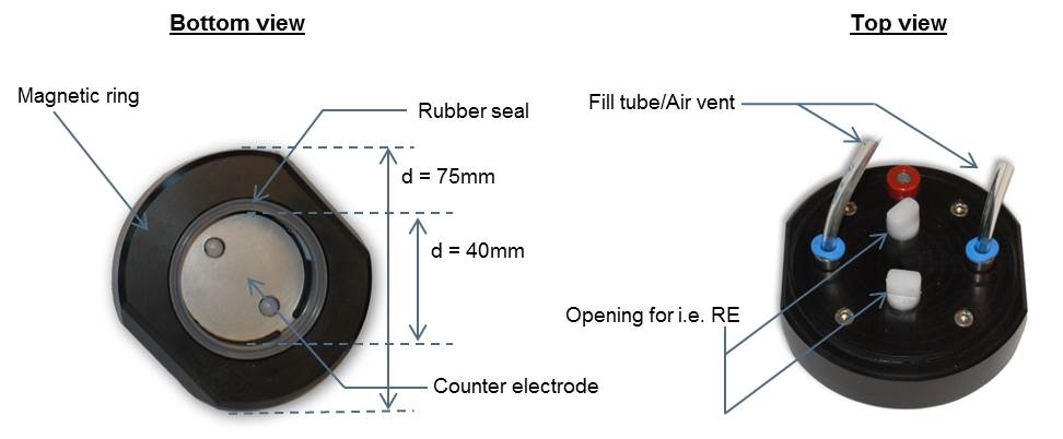
Figure 1: MCF Cell schematics
The bottom of the MCF Cell compartment consists of a 316L stainless steel (counter) electrode. The cell compartment can be filled with electrolyte using a syringe and a tube that leads directly into the cell. A similar tube allows air to escape to ensure a completely filled cell compartment. If desired a reference electrode can be placed near the surface of the coated steel sample that is the bottom of the cell, using either one of 2 holes designed for this purpose.
The MCF Cell is delivered in a kit that includes two MCF Cells and two syringes, one for each cell.
Figure 2 below shows a picture of a single MCF Cell clamped to a circular coated steel sample. The syringe is filled with electrolyte and attached to the fill tube, and a vent tube is attached to the other opening. Using the syringe, the electrolyte will flow into the cell compartment and the air (and excess electrolyte) will come out the vent tube. To prevent air pockets inside the cell compartment, the cell should be attached to the sample with the vent opening on the upper-side.
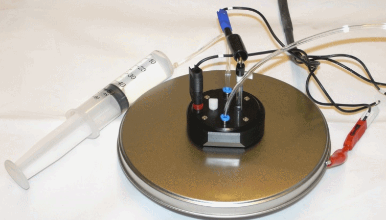
Figure 2: Connection of a single MCF Cell in a 3-electrode configuration (with a reference electrode)
The coated steel sample is the object of interest, so the potentiostat cell cable WE+S leads are connected directly to an uncoated part of the sample using an alligator clip. This WE+S connection needs to be directly to the steel substrate, so the coating has been removed at the connection point of the alligator clip. The potentiostat cell cable CE lead is connected to the counter electrode that forms the back of the MCF Cell, by inserting the banana in the red socket on the MCF Cell that leads to the stainless steel at the back of the cell compartment of the MCF Cell. A Ag/AgCl reference electrode is inserted into the appropriate opening and placed close to the surface of the coated steel sample. The potentiostat cell cable RE lead is connected to this reference electrode.
The situation where the bare steel of the coated steel sample is easily accessible, such as in the example above, is present in most laboratory testing situations. However, in the field the steel is most often coated and the base metal cannot be accessed to provide a direct contact for the WE (except by damaging the coating). For these situations, a second MCF Cell is supplied in the cell kit.
Figure 3 below shows two MCF Cells attached to a coated steel sample (circular). Both MCF Cells have their own syringe filled with electrolyte, attached to the fill tube at the bottom of each cell. Each MCF Cell is vented with a second tube to allow the air (and excess electrolyte) to escape. Squeezing each syringe will cause electrolyte to flow into the respective MCF Cell compartments. To prevent air pockets inside the cell compartments, the MCF Cells should be positioned so that the fill tubes are below the vent tubes.
NOTE: It is important for each MCF Cell to have its own electrolyte circuit in order to prevent galvanic coupling.
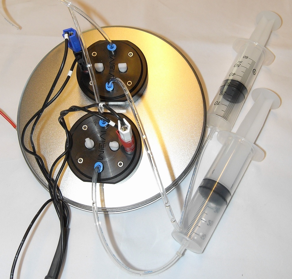
Figure 3: Connection of two MCF cells in a 2-electrode configuration
Because the base metal cannot be accessed, the potentiostat cell cable WE+S leads are connected to the stainless steel electrode of MCF1 (red socket). The potentiostat cell cable CE+RE leads are connected to the stainless steel electrode of MCF2 (red socket). In the depicted 2-electrode connection no reference electrode is used.
If reference electrodes are used to form a 4- electrode configuration, a reference electrode would be inserted in each of the MCF Cells using one of the 2 openings in each cell. The potentiostat cell cable S lead would be connected to the reference electrode in the MCF Cell connected to the potentiostat cell cable WE lead; the potentiostat cell cable RE lead would be connected to the reference electrode in the MCF Cell connected to the potentiostat cell cable CE lead.
When using a single MCF Cell on coated steel, a simple 2-electrode cell is formed. If a reference electrode is added and positioned near the surface of the coating, a 3-electrode cell is formed. Schematic representations of both situations are shown in Figure 4 below.
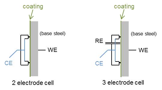
Figure 4: Schematic of 2- and 3-electrode cells formed using the MCF Cell
The reference electrode and counter electrode (back of the MCF Cell) are positioned on one side of the coating, the steel of the coated object is positioned on the other side of the coating. With this relatively simple cell EIS measurements can be carried out on the coated steel.
For EIS measurements the 2-electrode cell configuration is often the most practical. This is not just because of its simplicity, but also due to the nature of EIS measurements where an AC signal is applied around EOC[1], as well as because reference electrodes are notorious for introducing noise and their high impedance (that does not generally allow frequencies >50kHz).
It is of course also possible to carry out DC corrosion measurements (Tafel plot, Polarization Resistance, etc.), although these DC measurements are less common on coated steel samples and used more on un-coated steel samples. The 3-electrode cell is appropriate for most DC measurements; the potential at the surface of the sample is measured by the reference electrode.
[1] EOC = E-open cell, or open circuit potential; also referred to as OCP.
When both MCF Cells are placed on the coated steel an electrochemical cell is formed between the stainless steel electrodes in the back of both MCF Cells. Connecting the potentiostat cell cable WE+S leads to the stainless steel electrode in the back of MCF1, and the potentiostat cell cable leads CE+RE to the stainless steel electrode of MCF2, a 2-electrode configuration is formed.
If reference electrodes are placed in each of the MCF Cells, a 4-electrode cell is formed.
Schematic representations of both the 2- and 4- electrode configurations are shown in Figure 5 below.
Using two MCF Cells results in a current path that flows:
electrode MFC Cell1 → electrolyte 1 → coating → base steel → coating → electrolyte 2 → electrode MCF Cell2
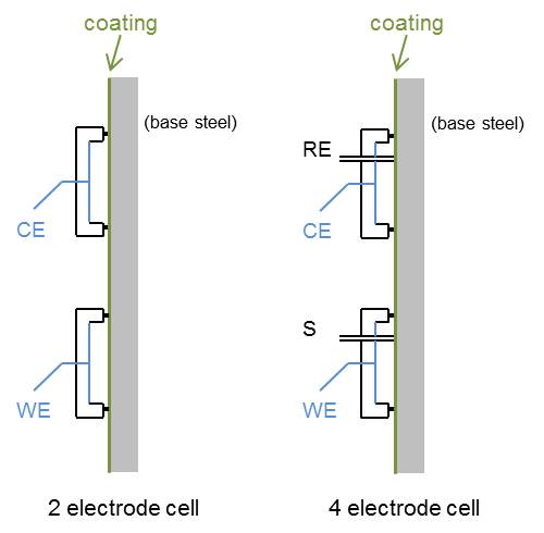
Figure 5: Schematic of 2- and 4-electrode cells formed using two MCF Cells
NOTE: When using two MCF Cells in the 2-electrode configuration, it should be taken into account that the corrosion of the coated steel should be the rate limiting process, preferably by some orders of magnitude. If not, then the measurement will show the resulting corrosion of the steel electrode in the MCF Cell rather than that of the (coated) steel sample. In this case the 4-electrode configuration should be used.
Two MCF Cells: AC measurement on coated steel
Using two MCF Cells in a 2-electrode configuration can be used for EIS measurements where an AC signal is applied around EOC. Such a measurement will result in 2*coating impedance, because the path of the current passes the coating twice.
The method parameters for all measurements are available on request from: info@ivium.com.
Using a single MCF Cell set-up as depicted in Figures 2 and 4 above, using a single MCF Cell, an EIS measurement was done on a coated steel sample in a 2-electrode configuration (no reference electrode used). The results are given in Figure 6.
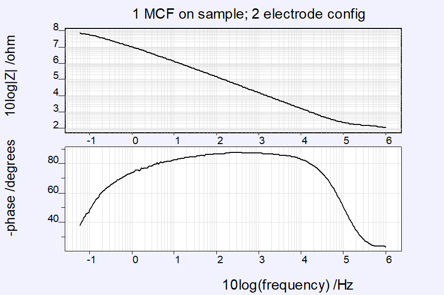
Figure 6: EIS scan on coated steel sample, 2-electrode configuration; parameters: 1MHz to 0.06 Hz, 20mV amplitude, E=0V vs. OCP [26feb/1538]
The measurement was repeated in a 3-electrode set-up, after a reference electrode was inserted. Due to the nature of the Ag/AgCl reference electrode used, the upper frequency of the 3-electrode measurement was limited to 100kHz. The results are given in Figure 7.
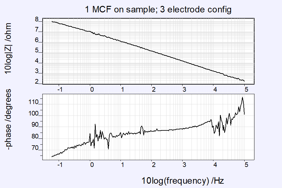
Figure 7: EIS scan on coated steel sample, 3-electrode configuration; parameters: 100kHz to 0.06 Hz, 20mV amplitude, E=0V vs. OCP [26feb1542]
When both measurements are plotted in the same graph (Figure 8), the results show exactly the same impedance values for both measurements. But the influence of the reference electrode can clearly be recognized when looking at the progress of the phase angle. This bears no influence on the impedance though.
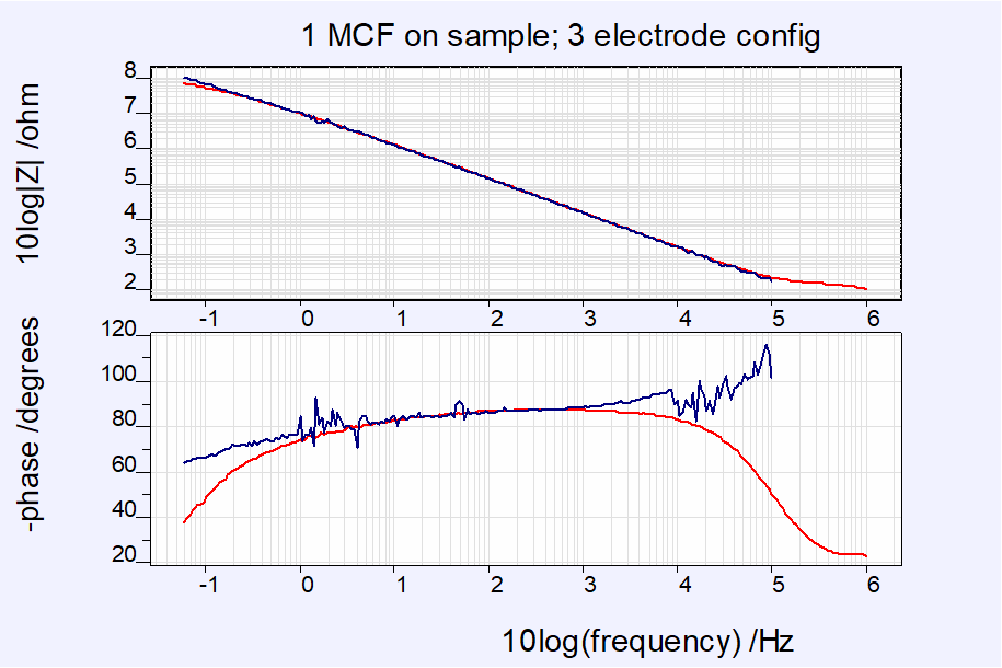
Figure 8: EIS scan on coated steel sample, 2- vs. 3-electrode configuration; parameters: 1MHz to 0.06 Hz, 20mV amplitude, E=0V vs. OCP [26feb1538/1542]
The results of the 2-electrode measurement are fitted using the Equivalent circuit evaluator (IviFit) in IviumSoft. When using the equivalent circuit for an ideal coating (Figure 9), the results are given in Figure 10.

Figure 9: Equivalent circuit for an ideal (new) coating
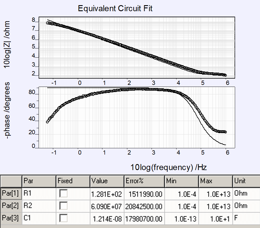
Figure 10: Ivifit results, ideal coating; measured with 1 MCF Cell, 2-electrode configuration
These fit results show an Rp (R2 in the model) of ca. 6.09 107 Ohm.
Using an accepted equivalent circuit model for an (older) coating under actual circumstances, as given in Figure 11, the results are given in Figure 12.
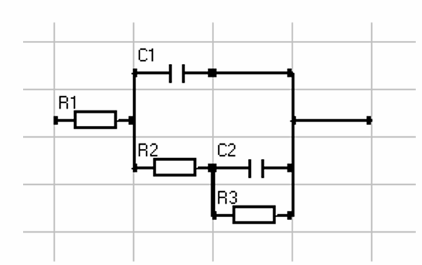
Figure 11: Equivalent circuit for an older (real) coating; R1 = Electrolyt resistance; C1 = Coating capacitance; R2 = Pore resistance; C2 = Double layer capacity; R3 = Polarization resistance.
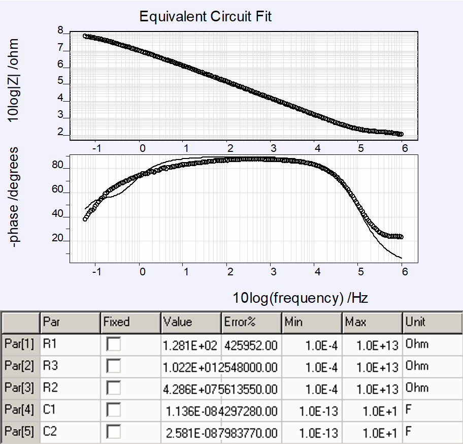
Figure 12: Ivifit results, real coating; measured with 1 MCF Cell, 2-electrode configuration
These fit results show an Rp (R3 in the model) of ca. 4.3 107 Ohm.
Using the set-up as depicted in figures 2 and 4 above with a single MCF Cell, a Tafel measurement is carried out on a coated steel sample. The results for a 2- and 3-electrode (with RE) measurement are shown in figure 13 below.
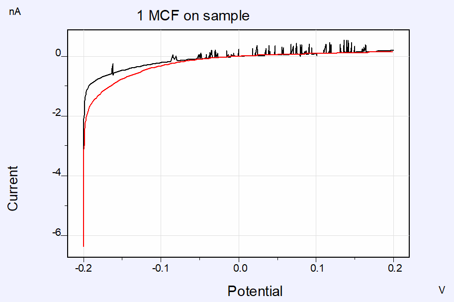
Figure 13: Tafel measurement on coated sample using 1 MCF Cell in 2- and 3-electrode configuration; parameters: scanrate 1mV/s at 0.125mV step; range -0.2V to 0.2V [26feb1545/1554]
Using the “Corrosion rate” analysis feature in IviumSoft, the rate of corrosion can be analysed using any one of three approaches:
– Slope analysis
– Tafel analysis
– Model analysis
Automatic analysis is possible, in which case IviumSoft itself determines the best parameters and markers. But optionally manual analysis is possible so that the user can choose the parameters and markers.
Normally the algorithm in IviumSoft can determine where to place the markers for the data range more accurately than the user, so automatic analysis is the best option. However, in certain specific cases, the user may decide to choose an alternative data range and placement of the markers (for example when the data is particularly noisy).
In Figure 14 below the Corrosion rate analysis is given for all 3 approaches.
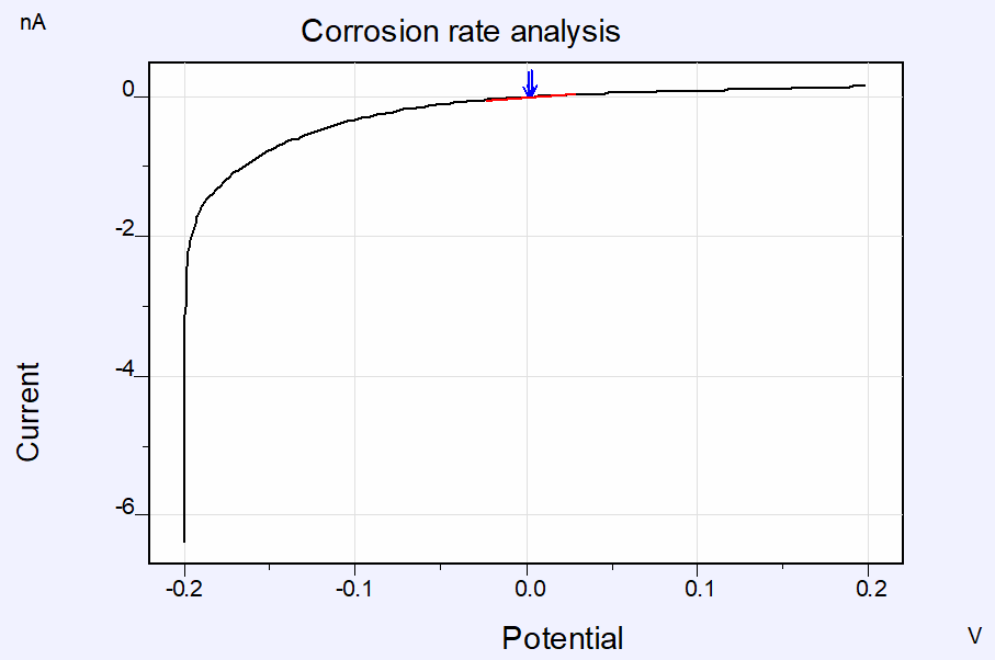
Figure 14a: Corrosion rate analysis of a Tafel measurement on coated sample using 1 MCF Cell in 2-electrode configuration; Automatic Slope analysis
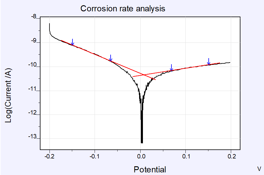
Figure 14b: Corrosion rate analysis of a Tafel measurement on coated sample using 1 MCF Cell in 2-electrode configuration; Automatic Tafel analysis
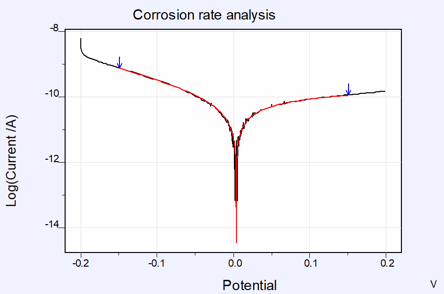
Figure 14c: Corrosion rate analysis of a Tafel measurement on coated sample using 1 MCF Cell in 2-electrode configuration; Automatic Model analysis
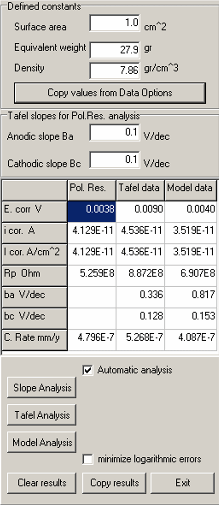
Figure 14d: Automatic corrosion rate analysis results; Default values are selected for steel-based sample.
The analysis of the Rp shows values close to one another in de order of 108 Ohm for all three analysis approaches.
The Slope analysis is generally regarded to be less precise (because of the limited E-range), however, in some cases, for example when evaluating noisy data, it is the most appropriate choice. the Model analysis is expected to yield the best results in most cases, because it applies the complete Butler-Volmer to the full data range.
The method parameters for all measurements are available on request from: info@ivium.com.
Using the set-up as depicted in figures 3 and 5 above with two MCF Cells, an EIS measurement was done on the same coated steel sample (see also paragraph 4.1) in a 2-electrode configuration (no reference electrode used). The results are given in Figure 15.
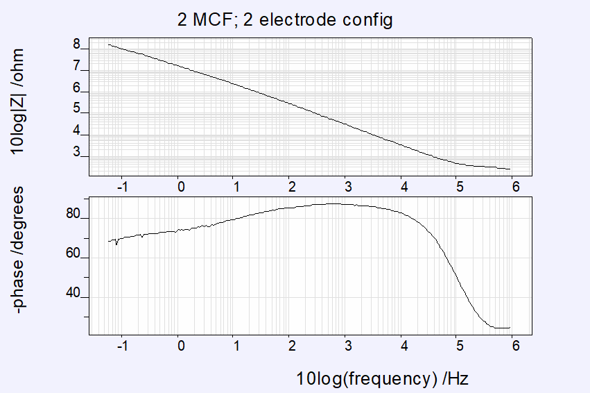
Figure 15: EIS scan on coated steel sample using 2 MCF Cells, 2-electrode configuration; parameters: 1MHz to 0.06 Hz, 20mV amplitude, E=0V vs. OCP [26feb/1560]
Comparing these results to the same measurement using a single MCF Cell, see Figure 16, it shows that the difference in measured impedance is indeed a factor of 2 as expected.
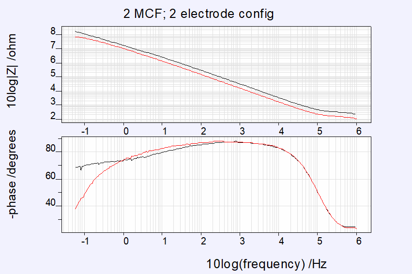
Figure 16: EIS scan on coated steel sample using 2 MCF Cells compared to using 1 MCF Cell (both in 2-electrode configuration)
Using the basic equivalent circuit model (figure 9), the results for the 2 MCF Cell measurement are fitted using the Equivalent circuit evaluator (IviFit) in IviumSoft.
The results are given in Figure 17.
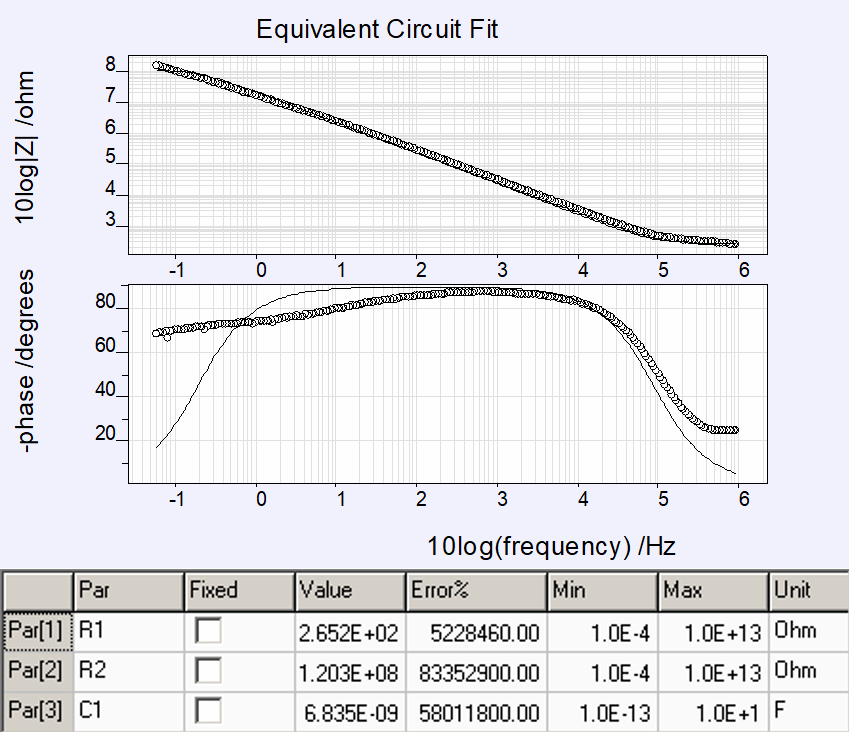
Figure 17: Ivifit results, real coating, measured with 2 MCF Cells, 2-electrode configuration
As shown, the Rp = ca. 1.2 108 Ohm. This is 2 x the Rp as measured with a single MCF Cell (Rp = ca. 6.09 107 Ohm, see figure 10).
Measurements in the field have been carried out to test and validate the MCF Cell performance. The same measurements were done with the cells that are normally used and repeated with the MCF Cells; the results are compared. All measurements have been done by ENDURES[2].
The measurement results comparing conventional cells with the MCF Cells are given in Figure 18.
[2] ENDURES, The Netherlands
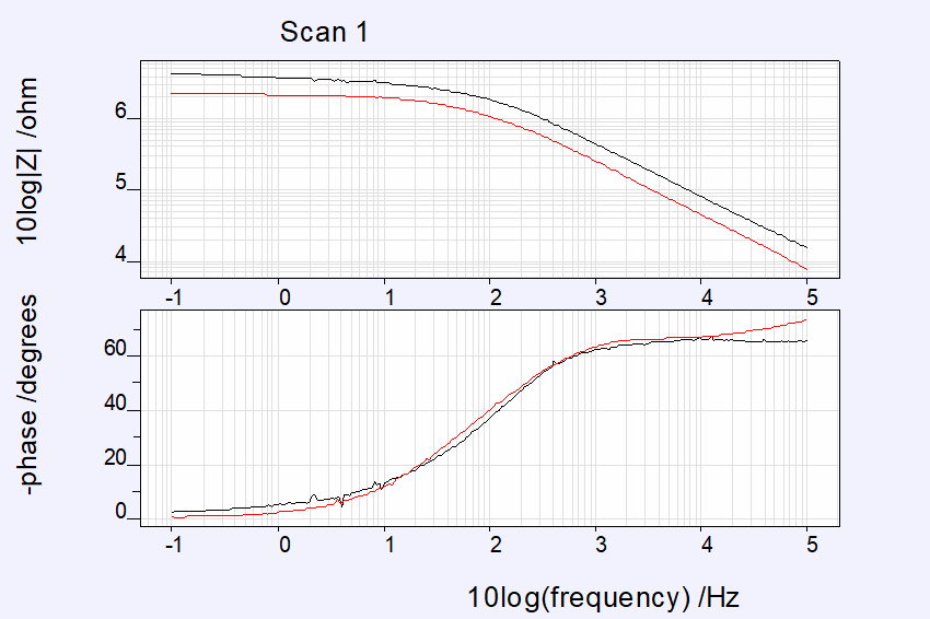
Figure 18: Measurement results comparing conventional cells with MCF Cells.
The results show identical behaviour for both cells. The difference in measured impedance is caused by a difference in surface area of the cells.
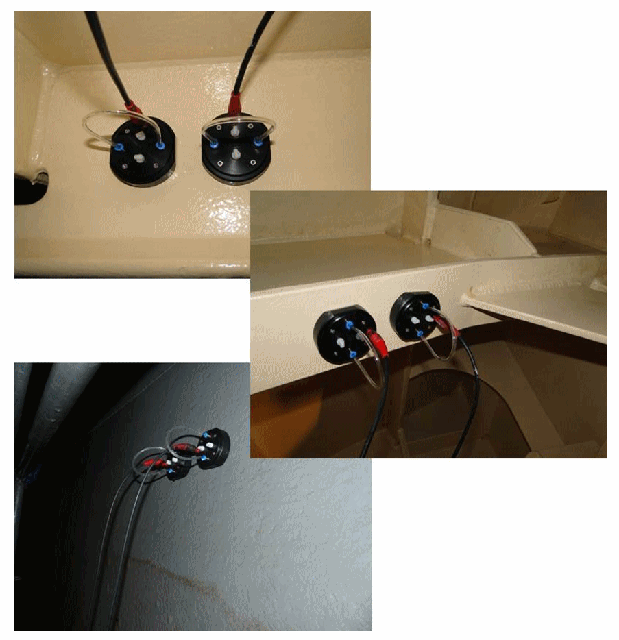
Figure 19: MCF Cells used during measurements in a ballas tank, bulk head, drinking water tank. [Photo’s courtesy of ENDURES]