A printable version of this electrochemical note is available here: IEN9 – How to use transmission lines or ladder networks in IviFit
Some objects have its impedance distributed over its length, its resistance / capacitance / inductance / etc are not interconnected at 1 point, but their mutual contactpoints are smeared out over the total length. An example is a transmission line, like an industrial coax cable that comes with listed properties as ohm, induction and capacity per meter. Such an object does not behave as a single R,L,C circuit, because its interconnections are spatially distributed over the total length. These systems may be modeled as a serial connected ensemble of many repeating blocks of equal circuits.
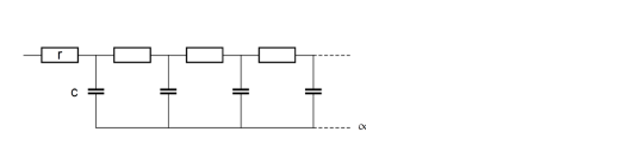
Figure 1: Example of a repeating RC circuit. Here, R is the series-, and C the parallel-element.
IviFit allows analysis EIS data for such models. These circuits contain a series and a parallel part. In the software, one can select a Zx element (x= 0..2) and put that parallel over the part of the circuit that is to be put in parallel.
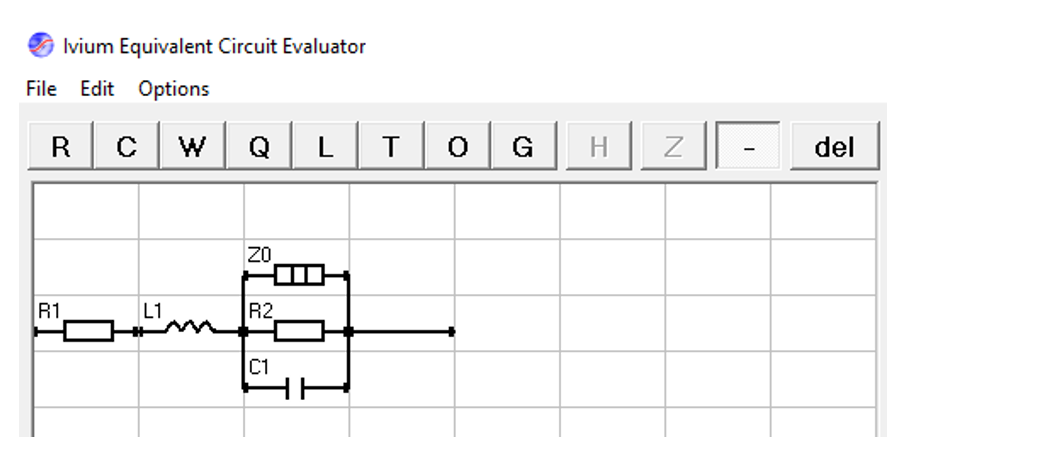
Figure 2: Defining a transmission line model in IviFit. Here, the R1,L1 are defined as series elements, and R3,C1 as parallel elements. The Zx is put parallel to the parallel elements. This configuration defines repeating blocks of the depicted circuit.
The Zx in the graphical editor has no impedance by itself, but is used to indicate the parallel part, and also transform the rest of the circuit into a repeating pattern. The Zx comes in 3 types, which can be selected on the Fit options:
Length will be determined in metre, whereas the other elements are defined per metre.