A printable version of this electrochemical note is available here: IEN2 – Bandwidth and stability settings explained
It is well known that bandwidth is a crucial parameter for any potentiostat/galvanostat. For the bandwidth/speed of an instrument, 3 factors play a role:
Usually when we talk about the potentiostat bandwidth, we mean the speed at which the signal is applied to the cell. Sometimes this is also referred to as rise-time, or stability.
We call this the stability setting because its main function is to ensure a stable applied signal. In theory, cells should be stable at even the highest speed stability setting. However, some cells have complex electronic properties – especially when high ohmic reference electrodes are used – that make it necessary to use a lower speed stability setting.
Most potentiostats/galvanostats have several selectable base bandwidth settings. For Ivium potentiostats, we have 3 user selectable settings high stability/standard/high speed = 50Hz/5kHz/maxDeviceBW respectively, and several internal settings that are used when automatic stability is selected.
The base BW is defined for so called “unity gain” or amplification factor=1, at which the instrument does not need to generate extra voltage to compensate for reference electrodes or losses. In many practical situations, reference electrodes are used, and there are losses in cables and electrolyte resistance, so it needs a higher amplification. That results in a bandwidth below the base bandwidth.
In potentiostatic mode, the reduction of base bandwidth is sometimes an issue for low ohmic cells. This is because the voltage losses over cable resistance and induction/contact resistance/etc., become higher than the cell impedance, so the potentiostat must compensate that with a very high gain amplification factor. That can drastically lower the practical bandwidth, and it may become necessary to manually select a higher bandwidth to retain a substantial signal.
In galvanostatic mode, there is the additional complication that the bandwidth also depends on the current range and the cell resistance. The bandwidth equals base bandwidth at zero cell resistance but decreases with increasing cell resistance. The rate of that decrease depends on the current range. Choosing a higher current range will lessen that decrease, so it is advisable to choose a high enough current range when high speed operation on low ohmic cells is required.
It is important to note that this bandwidth does not affect the accuracy of EIS measurements as that is determined by bandwidth of voltage and current measurement. Thus, it is possible to perform AC measurements beyond the signal bandwidth, providing there remains enough applied signal to allow a measurement.
This is a combination of the electrometer bandwidth and the signal procession/conversion bandwidth, usually several MHz at fastest settings. For the voltage measurement it is not necessary to create many decades of ranges (as we do for current measurements), and the bandwidth is about constant for all measurements.
Also, this is a combination of the current detection bandwidth and the signal procession/conversion bandwidth. For the higher current ranges, say 1mA and above, bandwidth is usually several MHz. However, a potentiostat can measure very low currents, sometimes down to femto-amperes. At such sensitive ranges, the measurement speed (bandwidth) is lower. Of course, one can sample as fast as one wants at any current range, but the result will not be useful to investigate phenomena faster than the bandwidth. Here we explain the reasons, and how to deal with this.
A current is usually measured using a resistor to convert the current to a voltage which can be recorded by a (digital) voltage measurement device. That resistor will have some parallel capacitance due to parasitic phenomena and design stability requirements, usually several pF. Suppose we have a current measurement system that generates 1V at its full range, its 1mA range uses 1kOhm, 1uA uses 1MOhm, etc. If that measurement resistor has a typical 20pF parallel capacity, the bandwidth will scale down to lower ranges: At CR=1µA, BW=8kHz; and at CR=1nA BW=8Hz, and so on.
BW=1/(2pi*R*C)
The consequence is that the lower current ranges cannot be used for high speed measurements. The EIS technique should be used in combination with AutoCR, so the software can select a CR that is compatible to the applied signal frequency. A rule of thumb is to remain a factor 5 below the current measurement bandwidth, so for the system above, the 1µA range should not be used above 1600Hz, otherwise measurement artefacts arise, rendering the measured impedance erroneous.
Sometimes, a technique called “post-gaining” is applied. This is where, instead of increasing the measurement resistor, the signal is amplified with a variable gain amplifier which retains bandwidth. However, that has the drawback of lower accuracy and increased noise, so its applicability is limited (see Ivium TechTip 1).
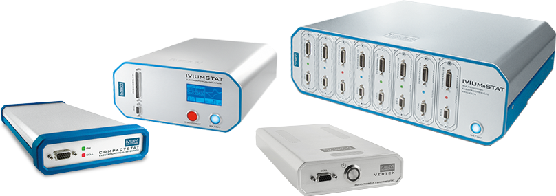
High speed potentiostats have been designed (like CompactStat and IviumStat) that have a very low parallel capacity over its measurement resistor, ca. 5pF. Also, low current boosters exist (LC module), with optimized cabling and shielding that have an even lower parasitic capacity, ca 0.1pF, so that the 1pA range can be measured with 50Hz bandwidth.
For the measurement of low impedances, it is not the capacitance that limits us, but the inductions in the cabling and measurement resistor (shunt) that become too dominant, and the signal will be attenuated. Of course, cables and shunts can be optimized but inevitably a limit will be reached. In practice, suppose you have 10nH residual inductance and you want to measure a 1mOhm resistor at 1% accuracy, your maximum usable frequency is R/(2pi*L*100)=160Hz.
The result accuracy for EIS can be improved by calibration. This numerically compensates for the parallel capacitance of the measurement resistor, which lowers that capacity to a lower effective value (similar for inductions at low ohmic cells). However, such a modeling operation has limits, and in practice this will only help a bit (say 1 magnitude). Moreover, this is a numerical procedure to improve the measurement accuracy; it does not make the actual signals larger. Beyond the bandwidth, the real signal gets lower down to a point that it cannot accurately be processed anymore.