A printable version of this application note is available here: A4.3 – Electrochemical impedance spectroscopy – Equivalent circuit fitting
Electrochemical cells can be modeled as a network of passive electrical circuit elements. This network is called an equivalent circuit. The impedance response of an equivalent circuit is fitted to the electrochemical impedance data to extract the values of the circuit components. Examples of electrochemical processes that respond like circuit elements are solution resistance and double layer capacitance. The Ivium Equivalent Circuit evaluator window can be accessed from the Analysis dropdown list and is depicted in Figure 1.
In this window the equivalent circuit model that represents the studied electrochemical system can be prepared in various ways:
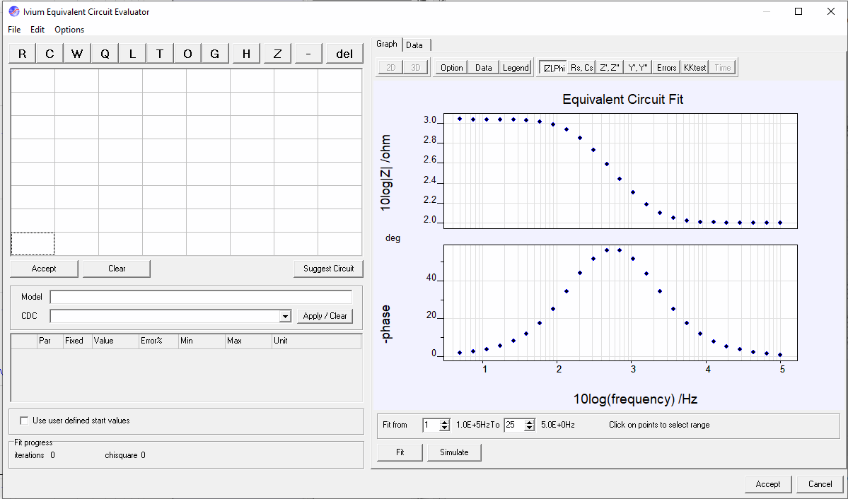
Figure 1: The Ivium Equivalent Circuit Evaluator window.
Define equivalent circuit
Manually draw the equivalent circuit
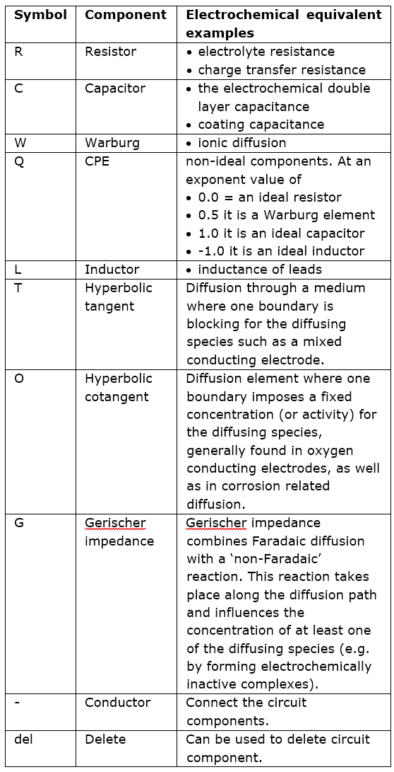
On the left, the graphical equivalent circuit editor grid is shown. It contains a toolbar with the selectable electrical components, see Table 1 for more details. To place a new element, click the desired component on the element toolbar and click it on the desired location in the grid. Components can be removed with the del-element. Vertical conductors are placed automatically between upper and lower neighbors. Where this is not wanted, keep an empty row between elements. Horizontal conductors are placed after selecting the “-” element. To simplify construction of a complete circuit, all ‘open ends’ on the right-hand side are automatically connected to each other. After the desired circuit is entered and accepted, clicking “Apply” will implement the model in the fitting engine.
Table 1: Details of the equivalent circuit components.
Type the circuit as text string
Instead of entering the circuit manually, a model can be entered manually in the “Model” field. Components can be placed in series using the “+” sign. Similarly, they can be placed in parallel by the “*” sign. Brackets can be used to combine more components.
Select a predefined equivalent circuit
Alternatively, predefined circuits might be loaded (load fit result) or be selected from the dropdown list in the CDC field. For systems with limited complication it is possible to let “Suggest circuit” automatically calculate an equivalent circuit.
Parameter list
After the desired circuit is entered and accepted, clicking “Apply” will implement the model in the fitting engine; the fit-able components and parameters are shown in the parameter list at the bottom left of the window.
The parameter list contains the details and fit settings of each of the components of the equivalent circuit:
Par(#): Name of the component, the symbol R, C, etc. and the sequence number corresponding to the Component grid and the Model/CDC expression.
Fixed: When checked, this parameter will not be changed by the fitting engine (not fitted) and the shown value will be used.
Value: Before the fit this shows the (default) start value. This value can be changed/entered manually before the fit is applied. If “Fixed” is checked it will not be changed during the fit; if “Fixed” is unchecked the Equivalent circuit modelling tool will generate its own starting values. This is convenient for the user, and it typically obtains better fit results. Therefore, by default the starting values are automatically generated. Optionally, the user can still apply their own starting values by checking “User defined Startvalues” and entering the start Value in the parameter list. The value is updated during fitting and contains the end value after fitting is complete.
Error: Calculates the error of the fitted parameter, which is only calculated after fitting is completed
Unit: Unit in which the parameter is expressed, e.g. Ohm, F.
Fitting
To the right of the Ivium Equivalent Circuit Evaluator window is the result window. There are various preset graphs that can be selected to plot the data in a convenient way. Below the graph the frequency range that is used for fitting can be set. The Fit button will start the fitting procedure. The simulate button will draw the impedance curve using the equivalent circuit and parameters values from the left hand of the window. Finally, the bottom right accept button closes the Equivalent circuit evaluator window. The present model and parameter values will be included in the data file. When the Equivalent Circuit Evaluator is started again with this data, the same results will be shown. The Cancel button closes the Equivalent Circuit Evaluator without saving the results. The present model and parameter values will not be included in the data.